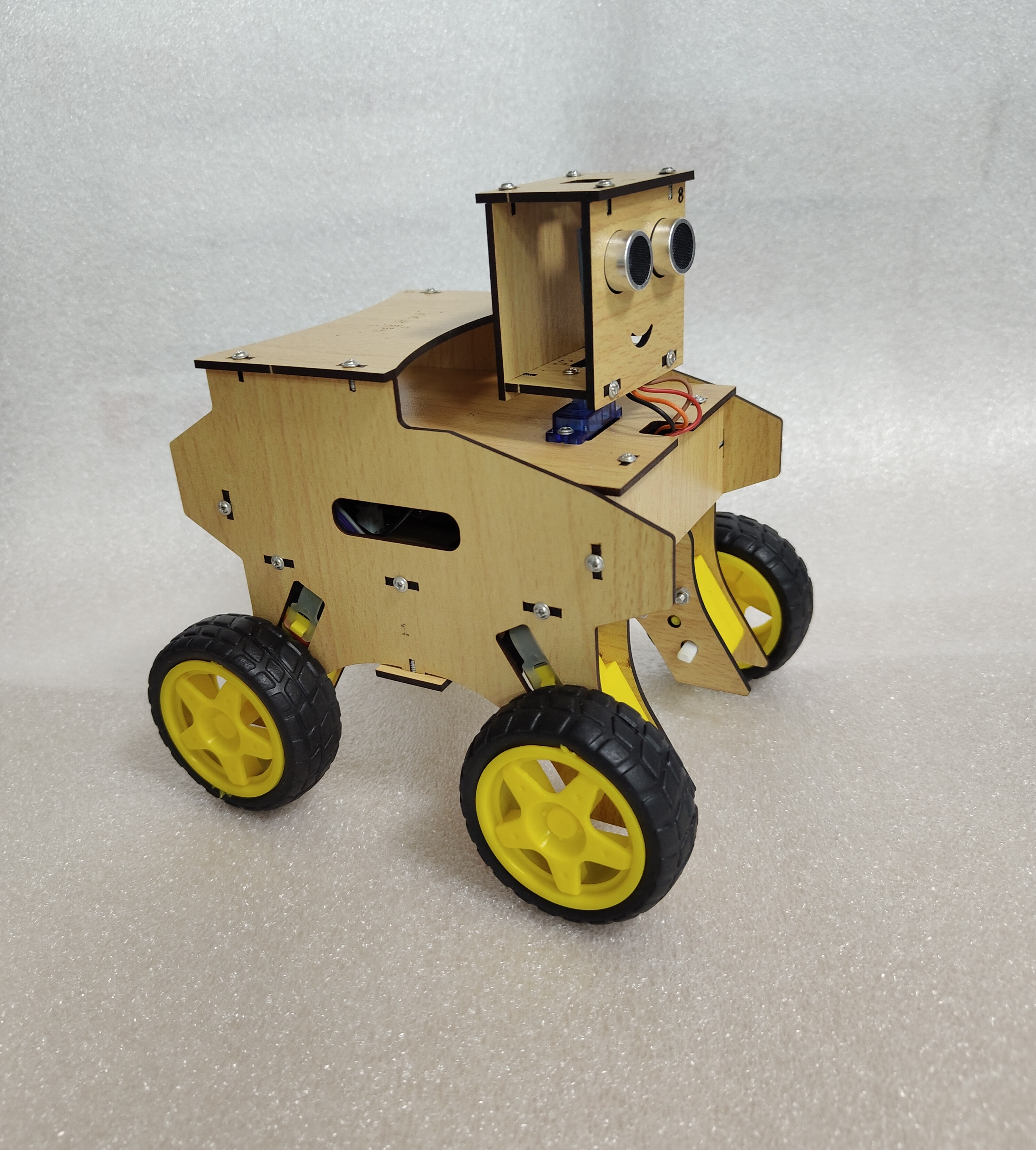
Smart Bot
Two in One : Obstacle Avoiding & Smart Phone Controlled
Shipping & returns FAQ
How long does shipping take?
Standard shipping is ₹79. Free shipping on orders of ₹1500 or more (merchandise subtotal after promo). Delivery typically 5–7 business days across India.
What payment methods do you accept?
UPI, credit/debit cards, and netbanking via Razorpay. Cash on Delivery is not available.
Can I get a GST invoice?
Yes. Add your GSTIN on checkout (optional). After payment you can print a receipt; for a full GST tax invoice with HSN, email support with your GSTIN and order id.
What is your return policy?
Unopened kits may be returned within 7 days of delivery. Opened educational kits are exchange-only for manufacturing defects. Contact support with your order id.
Is checkout secure?
Yes. Payments are processed by Razorpay over HTTPS. We never store your full card details on PSA servers.
Free delivery on merchandise subtotal ₹1,500+. See shipping & returns.
About This Kit
What's Included
- 1–12. Wooden structure parts (Plates 1 to 12)#1
- 13. Screwdriver#2
- 14. Battery holder#3
- 15. Rechargeable 18650 Battery#4
- 16. Wheels (4 pcs)#5
- 17. Gear motors (4 pcs)#6
- 18. Power switch#7
- 19. Charging module#8
- 20. Motor driver#9
- 21. Servo motor#10
- 22. Servo motor shaft connector#11
- 23. Ultrasonic sensor#12
- 24. Microcontroller board#13
- 25. Motor connecting wires#14
- 26. Servo motor wire#15
- 27. Female-to-female jumper connectors (4 pieces)#16
- 28. Ultrasonic sensor wire#17
- 29. Charging module wire#18
- 30. Black wire (female to open end)#19
- 31. Red wire (female to open end)#20
- 32. Red wire (open ends on both sides)#21
- 33. M3 × 30 bolt and nut set#22
- Mounting screws#23
Learning Outcomes
Learning outcomes will be listed when available for this kit.
Safety
- Safety Guidelines for Smart Builders • Handle electronic components carefully to avoid damage. • Always switch off power before making connections. • Do not short-circuit the battery terminals. • Follow the wiring color codes exactly as shown in the manual. Do not interchange wires of different colors, as incorrect wiring may damage the sensor, motor driver, or microcontroller. • Keep water away from electronic parts. • Ask for help if you are unsure about any step.
Build guide (22 steps)
Check All Kit Components Carefully
• Before starting the assembly, verify that all parts listed in the component list (1–34) are present in your STEM kit.
Separate the Wires
Carefully peel off and separate all individual ribbon wires and jumpers.
Mount Components on Plate-4
• Fix the Motor Driver (20), Microcontroller (24), Charging Module (19), and Battery Holder (14) onto Plate-4 using the Mounting Screws (34) and Screwdriver (13). • Follow the exact positions and orientations indicated on the board layout.
Connect Motor Wires
• Take two pairs (out of four) of the Motor Wires (25) and twist together the wires of the same color to form one combined set. • Make another combined set in the same way with the remaining pair. • Connect these two combined sets to the two motor output screw terminals of the Motor Driver (20). (Note: Wire colors in your kit may differ—maintain the same paired combination pattern.)
Attach Power Input Wire
• Attach the open end of the Red Wire (32) to the Power Input Port (+12V/VCC) of the Motor Driver (20).
Connect All Ground Wires
Connect the Charging Module
• Take the red wire from the Battery Holder (14) and the brown wire from the Charging Module Wire (29), twist them together, and keep this combined end aside for later use. • Connect the male connector of wire (29) into the female socket of the Charging Module (19), carefully aligning with the arrow mark on the connector. ⚠️ Warning: Do not reverse the connection—wrong orientation will damage the charging module.
Distribute 5V Power
Take the orange wire from Ultrasonic Sensor Wire (28), the red wire (31), and the middle wire from Servo Motor Wire (26), twist them together, and connect the combined wire to the 5V output port of the Motor Driver (20). This supplies power to the Ultrasonic Sensor (23), Microcontroller (24), and Servo Motor (21). (Note: Always follow the circuit diagram first, even if wire colours differ. The orange wire of (28) should be the outermost wire in the 4-wire group, opposite to the black wire.)
Power the Microcontroller
Take the red wire (31) and black wire (30) coming from the Motor Driver (20) and connect them to the Vin and G ports of the Microcontroller (24) respectively, using the attached female jumper connectors. Be very careful — red must go to Vin (+ve input) and black must go to G (ground or -ve input).
Connect Motor Control Pins
Connect the motor driver direction pins IN1, IN2, IN3, and IN4 to the microcontroller digital outputs D1, D2, D3, and D4 respectively using the female-to female connectors (27). (Note: The colours of the four control wires in your kit may be different from those shown in the image — always follow the circuit diagram.)
Connect Servo Control Wires
Take the remaining two wires of Servo Motor Wire (26) (the middle wire is already connected in Step 8) and connect them to digital pin D8 and G (Ground) of the Microcontroller (24). Keep other end free for later use. (Note: Remember the wire colours and their respective pins for correct connection to the Servo Motor (21) later.)
Connect Ultrasonic Signal Wires
Connect the middle two wires of Ultrasonic Sensor Wire (28) to the microcontroller digital pins D6 and D7 — red wire to D6 and brown wire to D7 (the outer two wires are already connected to the motor driver in earlier steps). The other ends will be connected to the Ultrasonic Sensor (23) in a later step.
motor wires
Pass the motor wires (25) through the holes in Plate 4 as shown in the picture.
Prepare Side Frames
Using Plate-1 and Plate-2 (from 1–12), Gear Motor (17), and M3 × 30 Bolt & Nut Set (33), assemble two side frames of the robot. Make sure the two frames are mirror images of each other as shown in the figure the motor wires face inward as shown in the picture.
Attach Side Frame to Plate-4
Fix one assembled side frame (from Step 14) to Plate-4 with the mounted electronics using Screws (34).
Attach Front and Back Supports
Fix Plate-6 and Plate-12 (from 1–12) as the back and front support plates to the assembly keeping Plate-12 on the front side near the Microcontroller (24). Align the slots in both plates with the charging module port and programming port, then attach the second side frame from Step 14 using Screws (34).
Insert Batteries and Test Power
First, recheck all connections carefully according to the circuit diagram and previous steps. Insert the 18650 Batteries (15) into the Battery Holder (14) — the flat side (negative) must touch the spring side of the holder. Now temporarily twist together the free end of the red wire from Step 5 and the free combined wire from Step 7 to test the circuit. If the red LED on the Motor Driver (20) turns ON, the connections are correct. If the LED does not turn ON, check that the batteries are placed properly and touching the metal contacts, verify the input and ground ports of the motor driver, and ensure the batteries are charged — you may use a mobile USB-C charger (voltage > 8.4V) on the charging port to test. After testing, disconnect these wires — the switch will be connected between them in a later step.
Mount Servo Motor and Top Plate:
Fix the Servo Motor (21) into the rectangular slot of Plate-3 (from 1–12) and connect its female connector to the male jumper of wire (26), ensuring the orange servo wire connects to digital pin D8 (from Step 11). Now attach Plate-3 as the top plate on the assembly from Step 17, keeping the servo motor facing toward the Microcontroller (24). Guide the two free power wires (red from Step 5 and combined wire from Step 7) through the rear hole of Plate-3 and pass the ultrasonic sensor wires (28) through the front slot as shown. Finally, connect the Switch (18) between these two power wires.
Connect Motors and Upload Code:
Connect all gear motors (17) to the female jumper ends of the motor wires (25) as shown in the picture. Upload the complete Arduino code to the Microcontroller (24) using a USB cable by following the instructions available on official website. Please scan QR code on the front page. After uploading, turn ON the Switch (18) and check that all four motors rotate in the forward direction. If any motor runs in reverse, simply swap its wire connections to correct the direction. Finally attach Plate-7 as shown to prevent the motor wires from falling down.
Assemble the Robot Head:
First connect the Ultrasonic Sensor (23) to its wire connector, ensuring the orange wire goes to VCC and the black wire to Ground. Press-fit the sensor into Plate-8 (from 1–12) as shown. Now select two side lever connectors from Servo Shaft Connectors (22) and attach them to Plate-10, keeping the circular holes facing outward. Next, form the head box using Plates 8, 9, 10, and 11, with Plate-9 on the top as shown in the figure. Finally, mount this head assembly onto the shaft of the Servo Motor (21) and secure it using the small screw provided in packet (22).
Attach Wheels and Finish Assembly
Firmly press all four Wheels (16) onto the motor shafts, then mount the top plate in position as shown in the picture. Your obstacle avoiding robot is now ready to run!
Charging Instruction:
Connect a mobile charger to the charging port to charge the robot. The indicator light will turn from red to blue when charging is complete.